GTAW
Gas tungsten arc welding
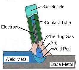
Gas tungsten arc welding (GTAW), also known as tungsten inert gas (TIG) welding, is an arc welding process that uses a nonconsumable tungsten electrode to produce the weld. The weld area is protected from atmospheric contamination by a shielding gas (usually an inert gas such as argon), and a filler metal is normally used, though some welds, known as autogenous welds, do not require it. A constant-current welding power supply produces energy which is conducted across the arc through a column of highly ionized gas and metal vapors known as a plasma.
GTAW is most commonly used to weld thin sections of stainless steel and light metals such as aluminum, magnesium, and copper alloys. The process grants the operator greater control over the weld than competing procedures such as shielded metal arc welding and gas metal arc welding, allowing for stronger, higher quality welds. However, GTAW is comparatively more complex and difficult to master, and furthermore, it is significantly slower than most other welding techniques. A related process, plasma arc welding, uses a slightly different welding torch to create a more focused welding arc and as a result is often automated.[1]
Contents
* 1 Development
* 2 Operation
o 2.1 Operation Modes
o 2.2 Safety
o 2.3 Applications
* 3 Quality
* 4 Equipment
o 4.1 Welding torch
o 4.2 Power supply
o 4.3 Electrode
o 4.4 Shielding gas
* 5 Materials
o 5.1 Aluminum and magnesium
o 5.2 Steels
o 5.3 Copper alloys
o 5.4 Dissimilar metals
* 6 Process variations
o 6.1 Pulsed-current
o 6.2 Dabber
o 6.3 Hot Wire
* 7 References
* 8 Notes
* 9 External links
Development
After the discovery of the electric arc in 1800 by Humphry Davy, arc welding developed slowly. C. L. Coffin had the idea of welding in an inert gas atmosphere in 1890, but even in the early 1900s, welding non-ferrous materials like aluminum and magnesium remained difficult, because these metals reacted rapidly with the air, resulting in porous and dross-filled welds.[2] Processes using flux covered electrodes did not satisfactorily protect the weld area from contamination. To solve the problem, bottled inert gases were used in the beginning of the 1930s. A few years later, a direct current, gas-shielded welding process emerged in the aircraft industry for welding magnesium.
This process was perfected in 1941, and became known as heliarc or tungsten inert gas welding, because it utilized a tungsten electrode and helium as a shielding gas. Initially, the electrode overheated quickly, and in spite of tungsten's high melting temperature, particles of tungsten were transferred to the weld. To address this problem, the polarity of the electrode was changed from positive to negative, but this made it unsuitable for welding many non-ferrous materials. Finally, the development of alternating current units made it possible to stabilize the arc and produce high quality aluminum and magnesium welds.[3]
Developments continued during the following decades. Linde Air Products developed water-cooled torches that helped to prevent overheating when welding with high currents.[4] Additionally, during the 1950s, as the process continued to gain popularity, some users turned to carbon dioxide as an alternative to the more expensive welding atmospheres consisting of argon and helium. However, this proved unacceptable for welding aluminum and magnesium because it reduced weld quality, and as a result, it is rarely used with GTAW today.
In 1953, a new process based on GTAW was developed, called plasma arc welding. It affords greater control and improves weld quality by using a nozzle to focus the electric arc, but is largely limited to automated systems, whereas GTAW remains primarily a manual, hand-held method.[5] Development within the GTAW process has continued as well, and today a number of variations exist. Among the most popular are the pulsed-current, manual programmed, hot-wire, dabber, and increased penetration GTAW methods.[6]
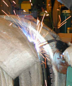
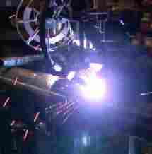
Operation
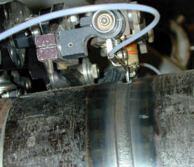
GTAW weld area
Manual gas tungsten arc welding is often considered the most difficult of all the welding processes commonly used in industry. Because the welder must maintain a short arc length, great care and skill are required to prevent contact between the electrode and the workpiece. Unlike most other welding processes, GTAW normally requires two hands, since most applications require that the welder manually feed a filler metal into the weld area with one hand while manipulating the welding torch in the other. However, some welds combining thin materials (known as autogenous or fusion welds) can be accomplished without filler metal; most notably edge, corner, and butt joints.
To strike the welding arc, a high frequency generator provides a path for the welding current through the shielding gas, allowing the arc to be struck when the separation between the electrode and the workpiece is approximately 1.5–3 mm (0.06–0.12 in). Bringing the two into contact in a "touch start" ("scratch start") also serves to strike an arc. This technique can cause contamination of the weld and electrode. Once the arc is struck, the welder moves the torch in a small circle to create a welding pool, the size of which depends on the size of the electrode and the amount of current. While maintaining a constant separation between the electrode and the workpiece, the operator then moves the torch back slightly and tilts it backward about 10–15 degrees from vertical. Filler metal is added manually to the front end of the weld pool as it is needed.[7]
Welders often develop a technique of rapidly alternating between moving the torch forward (to advance the weld pool) and adding filler metal. The filler rod is withdrawn from the weld pool each time the electrode advances, but it is never removed from the gas shield to prevent oxidation of its surface and contamination of the weld. Filler rods composed of metals with low melting temperature, such as aluminum, require that the operator maintain some distance from the arc while staying inside the gas shield. If held too close to the arc, the filler rod can melt before it makes contact with the weld puddle. As the weld nears completion, the arc current is often gradually reduced to allow the weld crater to solidify and prevent the formation of crater cracks at the end of the weld.[8][9]
Operation Modes
GTAW can use a positive direct current, negative direct current or an alternating current, depending on the power supply set up. A negative direct current from the electrode causes a stream of electrons to collide with the surface, generating large amounts of heat at the weld region. This creates a deep, narrow weld. In the opposite process where the electrode is connected to the positive power supply terminal, positively charged ions flow from the tip of the electrode instead, so the heating action of the electrons is mostly on the electrode. This mode also helps to remove oxide layers from the surface of the region to be welded, which is good for metals such as Aluminium or Magnesium. A shallow, wide weld is produced from this mode, with minimum heat input. Alternating current gives a combination of negative and positive modes, giving a cleaning effect and imparts a lot of heat as well.
Safety
Like other arc welding processes, GTAW can be dangerous if proper precautions are not taken. The process produces intense ultraviolet radiation, which can cause a form of sunburn and, in a few cases, trigger the development of skin cancer. Flying sparks and droplets of molten metal can cause severe burns and start a fire if flammable material is nearby, though GTAW generally produces very few sparks or metal droplets when performed properly.
It is essential that the welder wear suitable protective clothing, including leather gloves, a closed shirt collar to protect the neck (especially the throat), a protective long sleeve jacket and a suitable welding helmet to prevent retinal damage or ultraviolet burns to the cornea, often called arc eye. The shade of welding lens will depend upon the amperage of the welding current. Due to the absence of smoke in GTAW, the arc appears brighter than shielded metal arc welding and more ultraviolet radiation is produced. Exposure of bare skin near a GTAW arc for even a few seconds may cause a painful sunburn. Additionally, the tungsten electrode is heated to a white hot state like the filament of a lightbulb, adding greatly to the total radiated light and heat energy. Transparent welding curtains, made of a polyvinyl chloride plastic film, dyed in order to block UV radiation, are often used to shield nearby personnel from exposure.
Welders are also often exposed to dangerous gases and particulate matter. Shielding gases can displace oxygen and lead to asphyxiation, and while smoke is not produced, the arc in GTAW produces very short wavelength ultraviolet light, which causes surrounding air to break down and form ozone. Metals will volatilize and heavy metals can be taken into the lungs. Similarly, the heat can cause poisonous fumes to form from cleaning and degreasing materials. For example chlorinated products will break down producing poisonous phosgene. Cleaning operations using these agents should not be performed near the site of welding, and proper ventilation is necessary to protect the welder.[10]
Applications
While the aerospace industry is one of the primary users of gas tungsten arc welding, the process is used in a number of other areas. Many industries use GTAW for welding thin workpieces, especially nonferrous metals. It is used extensively in the manufacture of space vehicles, and is also frequently employed to weld small-diameter, thin-wall tubing such as those used in the bicycle industry. In addition, GTAW is often used to make root or first pass welds for piping of various sizes. In maintenance and repair work, the process is commonly used to repair tools and dies, especially components made of aluminum and magnesium.[11] Because the weld metal is not transferred directly across the electric arc like most open arc welding processes, a vast assortment of welding filler metal is available to the welding engineer. In fact, no other welding process permits the welding of so many alloys in so many product configurations. Filler metal alloys, such as elemental aluminum and chromium, can be lost through the electric arc from volatilization. This loss does not occur with the GTAW process. Because the resulting welds have the same chemical integrity as the original base metal or match the base metals more closely, GTAW welds are highly resistant to corrosion and cracking over long time periods, GTAW is the welding procedure of choice for critical welding operations like sealing spent nuclear fuel canisters before burial.[12]
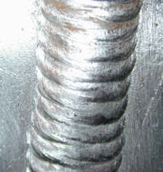
Quality
GTAW fillet weld
Engineers prefer GTAW welds because of its low-hydrogen properties and the match of mechanical and chemical properties with the base material. Maximum weld quality is assured by maintaining the cleanliness of the operation—all equipment and materials used must be free from oil, moisture, dirt and other impurities, as these cause weld porosity and consequently a decrease in weld strength and quality. To remove oil and grease, alcohol or similar commercial solvents may be used, while a stainless steel wire brush or chemical process can remove oxides from the surfaces of metals like aluminum. Rust on steels can be removed by first grit blasting the surface and then using a wire brush to remove any embedded grit. These steps are especially important when negative polarity direct current is used, because such a power supply provides no cleaning during the welding process, unlike positive polarity direct current or alternating current.[13] To maintain a clean weld pool during welding, the shielding gas flow should be sufficient and consistent so that the gas covers the weld and blocks impurities in the atmosphere. GTA welding in windy or drafty environments increases the amount of shielding gas necessary to protect the weld, increasing the cost and making the process unpopular outdoors.
Because of GTAW's relative difficulty and the importance of proper technique, skilled operators are employed for important applications. Welders should be qualified following the requirements of the American Welding Society or American Society of Mechanical Engineers. Low heat input, caused by low welding current or high welding speed, can limit penetration and cause the weld bead to lift away from the surface being welded. If there is too much heat input, however, the weld bead grows in width while the likelihood of excessive penetration and spatter increase. Additionally, if the welder holds the welding torch too far from the workpiece, shielding gas is wasted and the appearance of the weld worsens.
If the amount of current used exceeds the capability of the electrode, tungsten inclusions in the weld may result. Known as tungsten spitting, it can be identified with radiography and prevented by changing the type of electrode or increasing the electrode diameter. In addition, if the electrode is not well protected by the gas shield or the operator accidentally allows it to contact the molten metal, it can become dirty or contaminated. This often causes the welding arc to become unstable, requiring that electrode be ground with a diamond abrasive to remove the impurity.[14]
Equipment
GTAW torch with various electrodes, cups, collets and gas diffusers
GTAW torch, disassembled
The equipment required for the gas tungsten arc welding operation includes a welding torch utilizing a nonconsumable tungsten electrode, a constant-current welding power supply, and a shielding gas source.
Welding torch
GTAW welding torches are designed for either automatic or manual operation and are equipped with cooling systems using air or water. The automatic and manual torches are similar in construction, but the manual torch has a handle while the automatic torch normally comes with a mounting rack. The angle between the centerline of the handle and the centerline of the tungsten electrode, known as the head angle, can be varied on some manual torches according to the preference of the operator. Air cooling systems are most often used for low-current operations (up to about 200 A), while water cooling is required for high-current welding (up to about 600 A). The torches are connected with cables to the power supply and with hoses to the shielding gas source and where used, the water supply.
The internal metal parts of a torch are made of hard alloys of copper or brass in order to transmit current and heat effectively. The tungsten electrode must be held firmly in the center of the torch with an appropriately sized collet, and ports around the electrode provide a constant flow of shielding gas. Collets are sized according to the diameter of the tungsten electrode they hold. The body of the torch is made of heat-resistant, insulating plastics covering the metal components, providing insulation from heat and electricity to protect the welder.
The size of the welding torch nozzle depends on the amount of shielded area desired. The size of the gas nozzle will depend upon the diameter of the electrode, the joint configuration, and the availability of access to the joint by the welder. The inside diameter of the nozzle is preferably at least three times the diameter of the electrode, but there are no hard rules. The welder will judge the effectiveness of the shielding and increase the nozzle size to increase the area protected by the external gas shield as needed. The nozzle must be heat resistant and thus is normally made of alumina or a ceramic material, but fused quartz, a glass-like substance, offers greater visibility. Devices can be inserted into the nozzle for special applications, such as gas lenses or valves to improve the control shielding gas flow to reduce turbulence and introduction of contaminated atmosphere into the shielded area. Hand switches to control welding current can be added to the manual GTAW torches.[15]
Power supply
Gas tungsten arc welding uses a constant current power source, meaning that the current (and thus the heat) remains relatively constant, even if the arc distance and voltage change. This is important because most applications of GTAW are manual or semiautomatic, requiring that an operator hold the torch. Maintaining a suitably steady arc distance is difficult if a constant voltage power source is used instead, since it can cause dramatic heat variations and make welding more difficult.[16]
GTAW power supply
The preferred polarity of the GTAW system depends largely on the type of metal being welded. Direct current with a negatively charged electrode (DCEN) is often employed when welding steels, nickel, titanium, and other metals. It can also be used in automatic GTA welding of aluminum or magnesium when helium is used as a shielding gas. The negatively charged electrode generates heat by emitting electrons which travel across the arc, causing thermal ionization of the shielding gas and increasing the temperature of the base material. The ionized shielding gas flows toward the electrode, not the base material. Direct current with a positively charged electrode (DCEP) is less common, and is used primarily for shallow welds since less heat is generated in the base material. Instead of flowing from the electrode to the base material, as in DCEN, electrons go the other direction, causing the electrode to reach very high temperatures. To help it maintain its shape and prevent softening, a larger electrode is often used. As the electrons flow toward the electrode, ionized shielding gas flows back toward the base material, cleaning the weld by removing oxides and other impurities and thereby improving its quality and appearance.
Alternating current, commonly used when welding aluminum and magnesium manually or semi-automatically, combines the two direct currents by making the electrode and base material alternate between positive and negative charge. This causes the electron flow to switch directions constantly, preventing the tungsten electrode from overheating while maintaining the heat in the base material. Surface oxides are still removed during the electrode-positive portion of the cycle and the base metal is heated more deeply during the electrode-negative portion of the cycle. Some power supplies enable operators to use an unbalanced alternating current wave by modifying the exact percentage of time that the current spends in each state of polarity, giving them more control over the amount of heat and cleaning action supplied by the power source. In addition, operators must be wary of rectification, in which the arc fails to reignite as it passes from straight polarity (negative electrode) to reverse polarity (positive electrode). To remedy the problem, a square wave power supply can be used, as can high-frequency voltage to encourage ignition.[17]
Electrode
ISO
Class ISO
Color AWS
Class AWS
Color Alloy [18]
WP Green EWP Green None
WC20 Gray EWCe-2 Orange ~2% CeO2
WL10 Black EWLa-1 Black ~1% La2O3
WL15 Gold EWLa-1.5 Gold ~1.5% La2O3
WL20 Sky-blue EWLa-2 Blue ~2% La2O3
WT10 Yellow EWTh-1 Yellow ~1% ThO2
WT20 Red EWTh-2 Red ~2% ThO2
WT30 Violet ~3% ThO2
WT40 Orange ~4% ThO2
WY20 Blue ~2% Y2O3
WZ3 Brown EWZr-1 Brown ~0.3% ZrO2
WZ8 White ~0.8% ZrO2
The electrode used in GTAW is made of tungsten or a tungsten alloy, because tungsten has the highest melting temperature among pure metals, at 3,422 °C (6,192 °F). As a result, the electrode is not consumed during welding, though some erosion (called burn-off) can occur. Electrodes can have either a clean finish or a ground finish—clean finish electrodes have been chemically cleaned, while ground finish electrodes have been ground to a uniform size and have a polished surface, making them optimal for heat conduction. The diameter of the electrode can vary between 0.5 millimeter and 6.4 millimeters (0.02–0.25 in), and their length can range from 75 to 610 millimeters (3–24 in).
A number of tungsten alloys have been standardized by the International Organization for Standardization and the American Welding Society in ISO 6848 and AWS A5.12, respectively, for use in GTAW electrodes, and are summarized in the adjacent table. Pure tungsten electrodes (classified as WP or EWP) are general purpose and low cost electrodes. Cerium oxide (or ceria) as an alloying element improves arc stability and ease of starting while decreasing burn-off. Using an alloy of lanthanum oxide (or lanthana) has a similar effect. Thorium oxide (or thoria) alloy electrodes were designed for DC applications and can withstand somewhat higher temperatures while providing many of the benefits of other alloys. However, it is somewhat radioactive. Inhalation of the thorium grinding dust during preparation of the electrode is hazardous to one's health. As a replacement to thoriated electrodes, electrodes with larger concentrations of lanthanum oxide can be used. Electrodes containing zirconium oxide (or zirconia) increase the current capacity while improving arc stability and starting and increasing electrode life. In addition, electrode manufacturers may create alternative tungsten alloys with specified metal additions, and these are designated with the classification EWG under the AWS system.
Filler metals are also used in nearly all applications of GTAW, the major exception being the welding of thin materials. Filler metals are available with different diameters and are made of a variety of materials. In most cases, the filler metal in the form of a rod is added to the weld pool manually, but some applications call for an automatically fed filler metal, which often is stored on spools or coils.[19]
Shielding gas
GTAW system setup
As with other welding processes such as gas metal arc welding, shielding gases are necessary in GTAW to protect the welding area from atmospheric gases such as nitrogen and oxygen, which can cause fusion defects, porosity, and weld metal embrittlement if they come in contact with the electrode, the arc, or the welding metal. The gas also transfers heat from the tungsten electrode to the metal, and it helps start and maintain a stable arc.
The selection of a shielding gas depends on several factors, including the type of material being welded, joint design, and desired final weld appearance. Argon is the most commonly used shielding gas for GTAW, since it helps prevent defects due to a varying arc length. When used with alternating current, the use of argon results in high weld quality and good appearance. Another common shielding gas, helium, is most often used to increase the weld penetration in a joint, to increase the welding speed, and to weld metals with high heat conductivity, such as copper and aluminum. A significant disadvantage is the difficulty of striking an arc with helium gas, and the decreased weld quality associated with a varying arc length.
Argon-helium mixtures are also frequently utilized in GTAW, since they can increase control of the heat input while maintaining the benefits of using argon. Normally, the mixtures are made with primarily helium (often about 75% or higher) and a balance of argon. These mixtures increase the speed and quality of the AC welding of aluminum, and also make it easier to strike an arc. Another shielding gas mixture, argon-hydrogen, is used in the mechanized welding of light gauge stainless steel, but because hydrogen can cause porosity, its uses are limited.[20] Similarly, nitrogen can sometimes be added to argon to help stabilize the austenite in austentitic stainless steels and increase penetration when welding copper. Due to porosity problems in ferritic steels and limited benefits, however, it is not a popular shielding gas additive.[21]
Materials
Gas tungsten arc welding is most commonly used to weld stainless steel and nonferrous materials, such as aluminum and magnesium, but it can be applied to nearly all metals, with notable exceptions being lead and zinc. Its applications involving carbon steels are limited not because of process restrictions, but because of the existence of more economical steel welding techniques, such as gas metal arc welding and shielded metal arc welding. Furthermore, GTAW can be performed in a variety of other-than-flat positions, depending on the skill of the welder and the materials being welded.[22]
Aluminum and magnesium
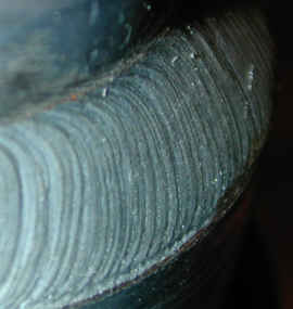
A TIG weld showing an accentuated AC etched zone
Closeup view of an aluminium TIG weld AC etch zone
Aluminum and magnesium are most often welded using alternating current, but the use of direct current is also possible, depending on the properties desired. Before welding, the work area should be cleaned and may be preheated to 175 to 200 °C (350 to 400 °F) for aluminum or to a maximum of 150 °C (300 °F) for thick magnesium workpieces to improve penetration and increase travel speed. AC current can provide a self-cleaning effect, removing the thin, refractory aluminium oxide (sapphire) layer that forms on aluminium metal within minutes of exposure to air. This oxide layer must be removed for welding to occur. When alternating current is used, pure tungsten electrodes or zirconiated tungsten electrodes are preferred over thoriated electrodes, as the latter are more likely to "spit" electrode particles across the welding arc into the weld. Blunt electrode tips are preferred, and pure argon shielding gas should be employed for thin workpieces. Introducing helium allows for greater penetration in thicker workpieces, but can make arc starting difficult.
Direct current of either polarity, positive or negative, can be used to weld aluminum and magnesium as well. Direct current with a positively charged electrode (DCEP) allows for high penetration, Short arc length (generally less than 2 mm or 0.07 in) gives the best results, making the process better suited for automatic operation than manual operation. Shielding gases with high helium contents are most commonly used with DCEN, and thoriated electrodes are suitable. Direct current with a negatively charged electrode (DCEN) is used primarily for shallow welds, especially those with a joint thickness of less than 1.6 millimeters (0.06 in). A thoriated tungsten electrode is commonly used, along with a pure argon shielding gas.[23]
[edit] Steels
For GTA welding of carbon and stainless steels, the selection of a filler material is important to prevent excessive porosity. Oxides on the filler material and workpieces must be removed before welding to prevent contamination, and immediately prior to welding, alcohol or acetone should be used to clean the surface. Preheating is generally not necessary for mild steels less than one inch thick, but low alloy steels may require preheating to slow the cooling process and prevent the formation of martensite in the heat-affected zone. Tool steels should also be preheated to prevent cracking in the heat-affected zone. Austenitic stainless steels do not require preheating, but martensitic and ferritic chromium stainless steels do. A DCEN power source is normally used, and thoriated electrodes, tapered to a sharp point, are recommended. Pure argon is used for thin workpieces, but helium can be introduced as thickness increases.[24]
Copper alloys
TIG welding of copper and some of its alloys is possible, but in order to get a seam free of oxidation and porosities, shielding gas needs to be provided on the root side of the weld. Alternatively, a special "backing tape", consisting of a fiberglass weave on heat-resistant aluminum tape can be used, to prevent air reaching the molten metal.
Dissimilar metals
Welding dissimilar metals often introduces new difficulties to GTAW welding, because most materials do not easily fuse to form a strong bond. However, welds of dissimilar materials have numerous applications in manufacturing, repair work, and the prevention of corrosion and oxidation. In some joints, a compatible filler metal is chosen to help form the bond, and this filler metal can be the same as one of the base materials (for example, using a stainless steel filler metal with stainless steel and carbon steel as base materials), or a different metal (such as the use of a nickel filler metal for joining steel and cast iron). Very different materials may be coated or "buttered" with a material compatible with a particular filler metal, and then welded. In addition, GTAW can be used in cladding or overlaying dissimilar materials.
When welding dissimilar metals, the joint must have an accurate fit, with proper gap dimensions and bevel angles. Care should be taken to avoid melting excessive base material. Pulsed current is particularly useful for these applications, as it helps limit the heat input. The filler metal should be added quickly, and a large weld pool should be avoided to prevent dilution of the base materials.[25]
Process variations
Pulsed-current
In the pulsed-current mode, the welding current rapidly alternates between two levels. The higher current state is known as the pulse current, while the lower current level is called the background current. During the period of pulse current, the weld area is heated and fusion occurs. Upon dropping to the background current, the weld area is allowed to cool and solidify. Pulsed-current GTAW has a number of advantages, including lower heat input and consequently a reduction in distortion and warpage in thin workpieces. In addition, it allows for greater control of the weld pool, and can increase weld penetration, welding speed, and quality. A similar method, manual programmed GTAW, allows the operator to program a specific rate and magnitude of current variations, making it useful for specialized applications.[26]
Dabber
The dabber variation is used to precisely place weld metal on thin edges. The automatic process replicates the motions of manual welding by feeding a cold filler wire into the weld area and dabbing (or oscillating) it into the welding arc. It can be used in conjunction with pulsed current, and is used to weld a variety of alloys, including titanium, nickel, and tool steels. Common applications include rebuilding seals in jet engines and building up saw blades, milling cutters, drill bits, and mower blades.[27]
Hot Wire
Welding filler metal can be resistance heated to a temperature near its melting point before being introduced into the weld pool. This increases the deposition rate of machine and automatic GTAW welding processes. More pounds per hour of filler metal is introduced into the weld joint than when filler metal is added cold and the heat of the electric arc introduces all of the heat. This process is used extensively in base material build up before machining, clad metal overlays, and hardfacing operations.
References
* American Welding Society (2004). Welding Handbook, Welding Processes Part 1. Miami Florida: American Welding Society. ISBN 0-87171-729-8.
* ASM International (2003). Trends in Welding Research. Materials Park, Ohio: ASM International. ISBN 0-87170-780-2
* Cary, Howard B. and Scott C. Helzer (2005). Modern Welding Technology. Upper Saddle River, New Jersey: Pearson Education. ISBN 0-13-113029-3.
* Jeffus, Larry (2002). Welding: Principles and Applications. Thomson Delmar. ISBN 1-4018-1046-2.
* Lincoln Electric (1994). The Procedure Handbook of Arc Welding. Cleveland: Lincoln Electric. ISBN 99949-25-82-2.
* Messler, Robert W. (1999). Principles of Welding. Troy, New York: John Wiley & Sons, Inc. ISBN 0-471-25376-6
* Minnick, William H. (1996). Gas Tungsten Arc Welding handbook. Tinley Park, Illinois: Goodheart-Willcox Company. ISBN 1-56637-206-2.
* Weman, Klas (2003). Welding processes handbook. New York: CRC Press LLC. ISBN 0-8493-1773-8.
Notes
1. ^ Weman, 31, 37–38
2. ^ Cary and Helzer, 5–8
3. ^ Lincoln Electric, 1.1-7–1.1-8
4. ^ Cary and Helzer, 8
5. ^ Lincoln Electric, 1.1-8
6. ^ Cary and Helzer, 75
7. ^ Lincoln Electric, 5.4-7–5.4-8
8. ^ Jeffus, 378
9. ^ Lincoln Electric, 9.4–7
10. ^ Cary and Helzer, 42, 75
11. ^ Cary and Helzer, 77
12. ^ ASM International, "Optimizing Long-Term Stainless Steel Closure Weld Integrity in DOE Standard Spent Nuclear Canisters" by Arthur D. Watkins and Ronald E. Mizia, 424–426
13. ^ Minnick, 120–21
14. ^ Cary and Helzer, 74–75
15. ^ Cary and Helzer, 71–72
16. ^ Cary and Helzer, 71
17. ^ Minnick, 14–16
18. ^ MarkeTech International
19. ^ Cary and Helzer, 72–73
20. ^ Minnick, 71–73
21. ^ Jeffus, 361
22. ^ Weman, 31
23. ^ Minnick, 135–49
24. ^ Minnick, 156–69
25. ^ Minnick, 197–206
26. ^ Cary and Helzer, 75–76
27. ^ Cary and Helzer, 76–77
Posted by LintanX at 1:47 AM 0 comments
Labels: Welding Technology
» Read More...